

LOD in BIM (Level of Development) defines how complete and reliable each element of a building information model is at a given project stage. It runs from LOD 100 (a conceptual placeholder) to LOD 400 (a fabrication-ready element), with LOD 500 reserved for field-verified models. Choosing the right LOD for each phase is what keeps coordination, detailing and fabrication aligned.
For general contractors, fabricators and design teams in the U.S., LOD is not an academic label. It decides what you can measure from a model, which clashes you can trust, and whether a steel or rebar model can go straight to the shop. This guide explains each level, compares LOD 300, 350 and 400 side by side, and shows how our team at ADIPSA applies them when delivering clash-free BIM models for U.S. contractors.
Key takeaways
- LOD measures how much the project team can rely on a model element, not just how detailed it looks.
- LOD 300 is the usual target for design coordination: size, shape and location are accurate and measurable.
- LOD 350 adds the interfaces between systems (supports, connections, clearances), which is why it is the standard for MEP and structural clash detection.
- LOD 400 is fabrication level: the model carries the detail needed for shop drawings, CNC files and assembly.
- LOD is assigned per element and per phase in the BIM Execution Plan, never as one number for the whole model.
What is LOD in BIM?
LOD in BIM stands for Level of Development: a scale that describes the geometry and information an element must contain at a specific milestone, and therefore how far other team members can rely on it. An LOD 300 beam, for example, can be used to measure quantities and check clearances; an LOD 100 beam cannot.
The concept was introduced by the American Institute of Architects (AIA) in its BIM contract exhibits and is now maintained in detail by BIMForum through the BIMForum LOD Specification, which is updated every year and is the most widely used reference in the U.S. market.
Level of Development vs. Level of Detail
The two terms are often confused. Level of Detail describes how much graphic detail an element shows. Level of Development describes how much the geometry and data have been thought through and can be trusted for decisions. A model can look highly detailed and still be unreliable if dimensions, locations or specifications have not been confirmed. Contracts and BIM Execution Plans should always refer to Level of Development.
What are the LOD levels in BIM?
There are six commonly referenced levels: LOD 100, 200, 300, 350, 400 and 500. Each one builds on the previous level, adding reliability and information, except LOD 500, which refers to field verification rather than further development.
| LOD | What the model element contains | Typical use |
|---|---|---|
| LOD 100 | A symbol or generic placeholder. Information is derived from other elements (for example, cost per square foot). | Conceptual design, massing, early cost estimates |
| LOD 200 | A generic system or object with approximate quantity, size, shape, location and orientation. | Schematic design, preliminary system layouts |
| LOD 300 | A specific element with accurate quantity, size, shape, location and orientation, measurable directly from the model. | Design development, construction documents, design coordination |
| LOD 350 | LOD 300 plus the interfaces with other systems: supports, hangers, connections and required clearances. | Construction-level coordination and clash detection |
| LOD 400 | A specific element with the detailing, fabrication, assembly and installation information needed to build it. | Shop drawings, fabrication, CNC files, prefabrication |
| LOD 500 | A field-verified representation of the element as built. Not a further step of development. | As-built records, facility management |
LOD 300 vs. LOD 350 vs. LOD 400: what is the difference?
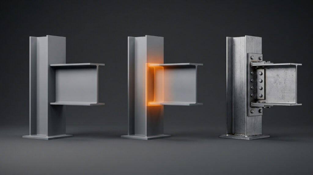
The difference is the purpose each level serves. LOD 300 answers “is the design correct and measurable?”, LOD 350 answers “do the systems fit together?”, and LOD 400 answers “can this be fabricated and installed exactly as modeled?”. Most construction-phase problems appear when a team expects the answer of one level from a model built to another.
| Criteria | LOD 300 | LOD 350 | LOD 400 |
|---|---|---|---|
| Main question it answers | Is the design accurate? | Do the systems fit together? | Can it be fabricated? |
| Geometry | Exact size, shape and location | Same as 300, plus interfaces between systems | Fabrication detail: connections, plates, bolts, welds, bar bends |
| Structural steel example | Beams and columns with correct profiles and positions | Connections represented as zones that other trades must respect | Every plate, bolt, cope and weld modeled for shop drawings |
| MEP example | Ducts and pipes sized and routed | Hangers, supports, insulation and access clearances included | Spool-level segments ready for prefabrication |
| Reliable for clash detection? | Partially: hard clashes between main elements | Yes: hard and clearance clashes | Yes, at trade and fabrication level |
| Typical owner | Architect and engineer of record | Trade contractors and BIM coordinator | Fabricators and detailers |
Which LOD do you need for clash detection?
For reliable clash detection during preconstruction, the target is LOD 350 for the systems being coordinated. LOD 300 finds hard clashes between main elements, but it misses the hangers, supports, insulation and maintenance clearances where most field conflicts actually happen.
This is especially critical when coordinating MEP systems in dense ceiling spaces, where a duct that clears a beam at LOD 300 can still collide with that beam’s connection or with a pipe hanger once LOD 350 elements are added. If you want to understand how conflicts are classified, see our explanation of how hard and soft clashes are detected.
Which LOD do you need for steel and rebar fabrication?
Fabrication requires LOD 400. At this level, the model contains everything a shop needs: exact member lengths, connection components, bolt and weld information, and, for concrete, bar shapes, bends and placement. Shop drawings, bills of materials and CNC or DSTV files are generated directly from it.
- Structural steel: the detailer develops LOD 400 steel models for fabrication, typically in Tekla Structures or Advance Steel. This is also where the model feeds production: see how LOD 400 models feed shop drawings and CNC files.
- Reinforced concrete: fabrication-ready rebar models allow placing drawings and bar bending schedules to be extracted with consistent quantities.
A practical example: in the 116.77-ton SMP Office steel structure, our team carried the model from structural design through steel detailing, so the connections defined during design were the same ones delivered to the fabricator.
Who defines the LOD in a project?
The LOD for each element and phase is defined in the BIM Execution Plan (BEP), usually through a Model Element Table that lists every building system, the LOD required at each milestone, and the party responsible for modeling it. The owner or general contractor sets the requirements; designers, trade contractors and detailers commit to delivering them.
The best moment to set these targets is before modeling begins. Our article on setting LOD targets at project kickoff explains why late definitions lead to rework.
How to specify LOD correctly: a 5-step checklist
- List the model uses first. Define what the model will be used for in each phase (estimating, coordination, fabrication, facility management) before assigning any LOD.
- Assign LOD per element, not per model. Foundations may reach LOD 400 while finishes remain at LOD 200 in the same phase.
- Name the model element author. Every element needs a responsible party at each milestone to avoid gaps between design and trade models.
- Reference a published standard. Cite the edition of the BIMForum LOD Specification in the contract and BEP so everyone uses the same definitions.
- Verify at each milestone. Include LOD checks in model reviews, as part of the five stages of a coordination workflow.
Common mistakes when specifying LOD
- Asking for “LOD 400 everywhere”. It raises modeling cost without adding value for elements that will never be prefabricated.
- Treating LOD 500 as a higher level of detail. LOD 500 is about field verification, not more geometry.
- Coordinating at LOD 300 and expecting a clash-free installation. Without LOD 350 interfaces, supports and clearances remain unchecked.
- Confusing detail with reliability. A visually rich family pulled from a library is not LOD 350 or 400 unless its dimensions and data have been verified for the project.
- Leaving LOD out of the contract. If it is not in the BEP or the model exhibit, there is no agreed deliverable to review against.

How ADIPSA works with LOD on U.S. projects
Our engineering team in Panama works in the same business hours as U.S. project teams and delivers models to the LOD defined in each BIM Execution Plan: LOD 300 and 350 for coordination, and LOD 400 for steel and rebar detailing. Because structural design, BIM coordination and detailing are developed by one team, the information added at each level is carried forward instead of being remodeled by a different firm. If you are evaluating external support, this overview of what outsourcing BIM modeling delivers can help.
Need a model developed to a specific LOD?
Send us your drawings and BIM Execution Plan and our team will propose the scope and schedule for your project, from LOD 350 coordination models to LOD 400 fabrication models. Talk to our BIM coordination team.
📞 +507 6126-1554 | 💬 Chat on WhatsApp
Working in U.S. business hours from Panama.
Frequently asked questions about LOD in BIM
Is LOD 500 the same as an as-built model?
Yes, in practice. LOD 500 describes a model element that has been verified in the field for size, shape, location, quantity and orientation. It is used for as-built records and facility management, and it is not a more detailed version of LOD 400.
What LOD is required for construction documents?
Construction documents are usually developed at LOD 300, because elements must be accurate and measurable. Systems that will be coordinated by trades before installation are then advanced to LOD 350 during preconstruction.
Does a higher LOD always mean a better model?
No. A higher LOD means more effort and cost. The right LOD is the lowest level that supports the model use required in each phase. Over-modeling adds time without reducing risk.
Why is LOD 350 required for MEP coordination?
Because MEP conflicts usually happen at supports, hangers, insulation and access clearances, not at the centerline of a duct or pipe. LOD 350 is the first level that includes those interfaces, so clash detection results can be trusted.
What LOD is needed for steel shop drawings?
LOD 400. Shop drawings, bolt lists and CNC files are extracted from a model where every connection component is defined, which only happens at fabrication level.